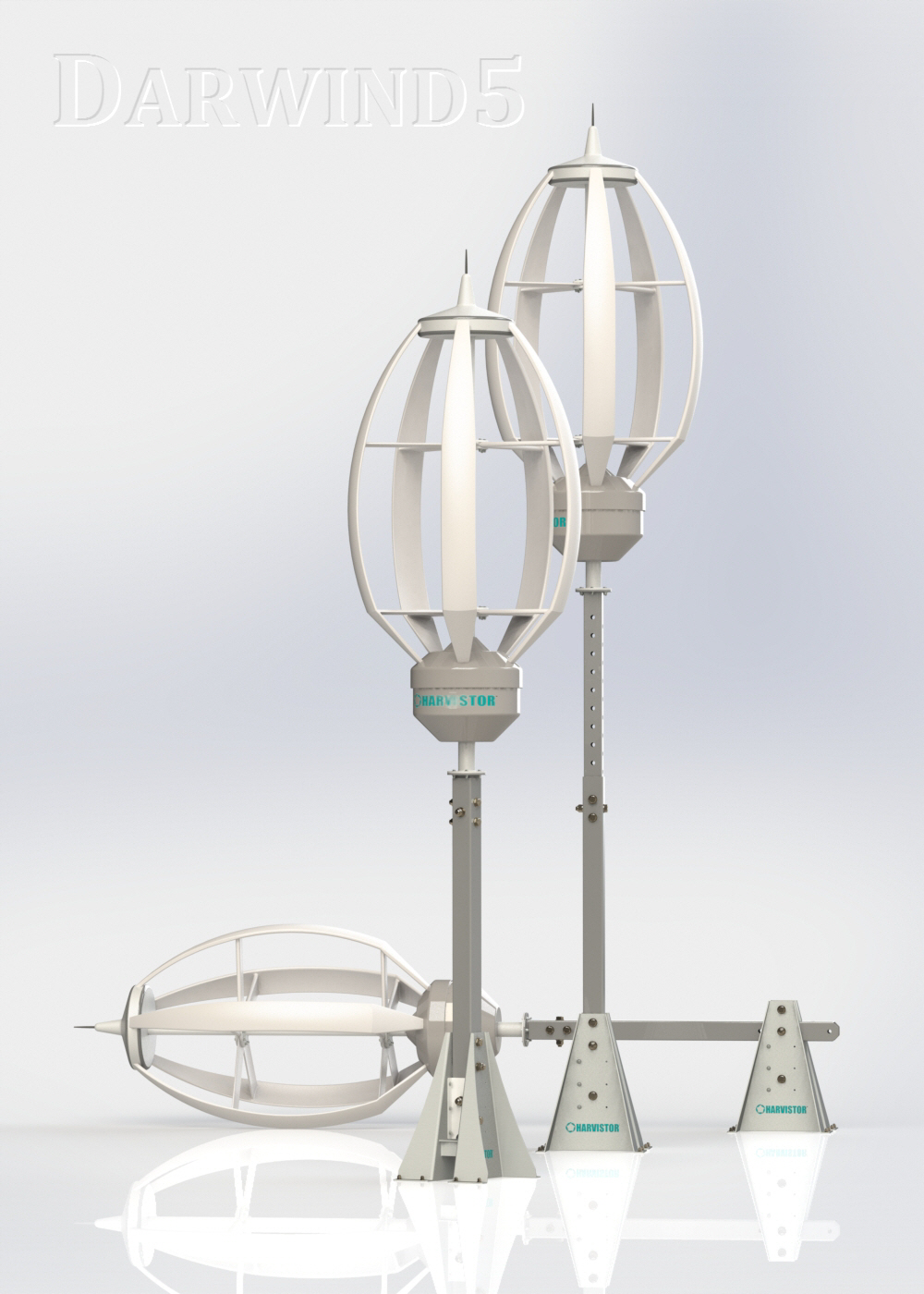
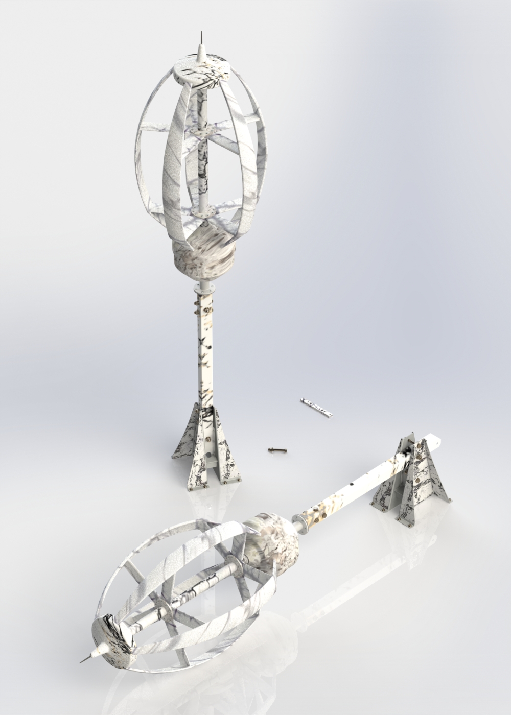
Photo-Realistic Rendering of the Toy with 3D-Printed Parts
A few months ago I collaborated with Hardi Meybaum (CEO of Grabcad.com ) on a fun CAD design project, and recently received a nice email from Hardi that WIRED Magazine is doing an interview with him. He asked if I could upload a few photo-realistic SolidWorks CAD software renderings of the final design.
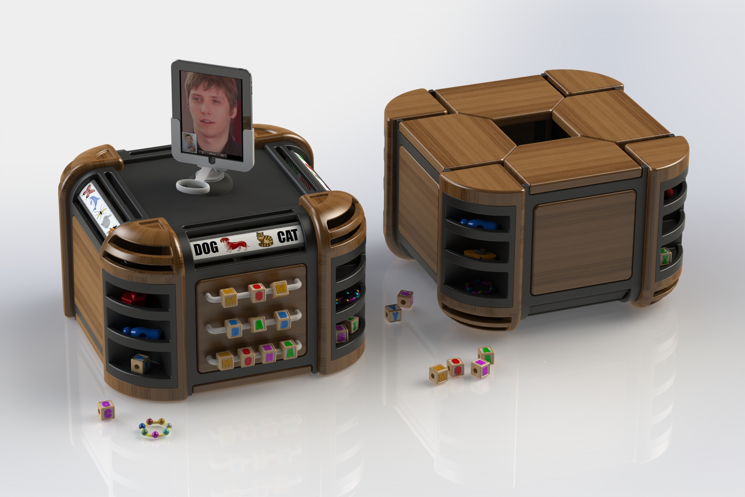
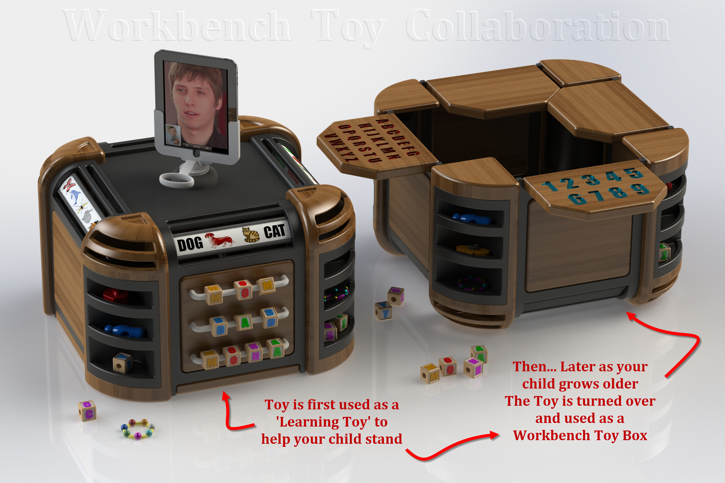
The ‘Stand-Up’ Toy Concept that Turns Over to become a ‘Workbench’ Toy Box
[ Click on Image to See a Larger View ]
Hardi is a very smart individual, and unlike many CEOs, he had the forethought to test out the new Collaboration Area beta himself with someone like me, that he had never met in person, and ‘literally’ lived on the other side of the Earth.
Therefore, the purpose of this Toy Design Project was to test out GrabCAD’s ‘Workbench‘ Collaboration Area to see what existing items worked, and also to see what additional items would be helpful for individuals whom wished to collaborate on CAD design projects around the world.
Hardi later mentioned to me in an email, that during the process I had uploaded a video to better show our concept ideas, and he decided it would be a good idea to add Video Support Capabilities to the GrabCAD Workbench Area.
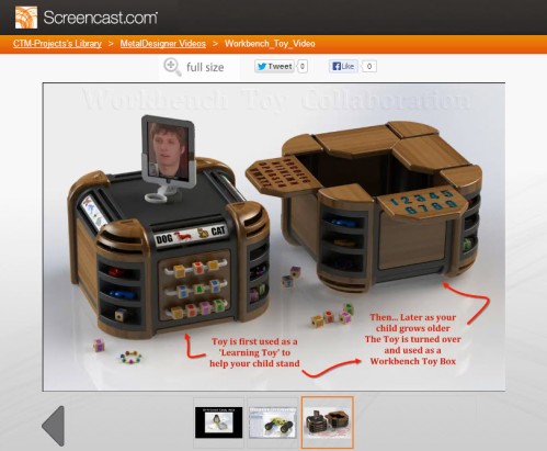
Example Video Showing the Workbench Toy Box Design
ScreenCast.com Example Video : http://www.screencast.com/t/9BoSo7IRu
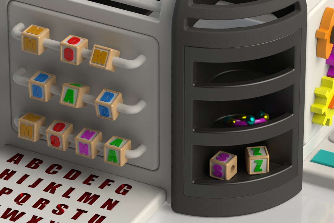
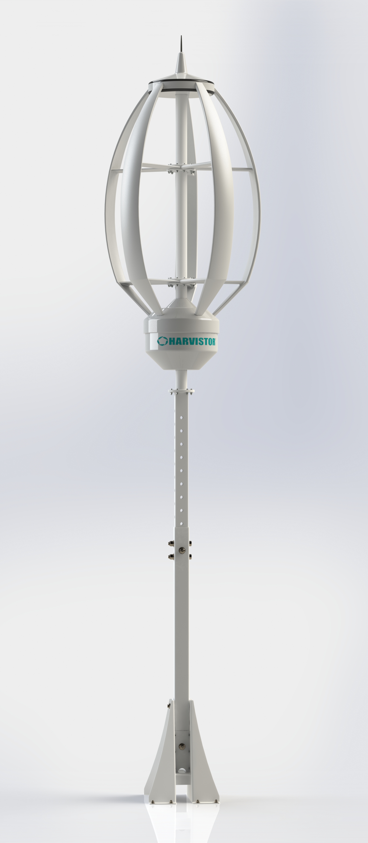
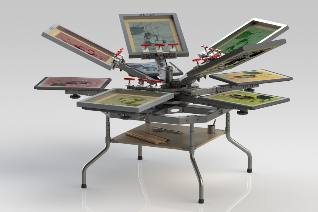
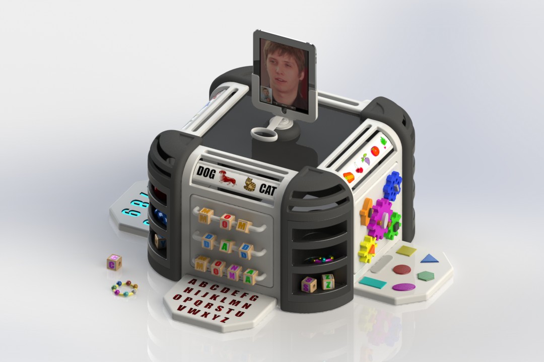
Close-Up View of showing some of the Learning & Play items on the Toy
Hardi wanted to design a toy for his newborn daughter, and I wished to incorporate 3D-Printed parts into the design … In the end we came up with a Toy Design that could be made out of wood and/or could have some ( or all ) of the parts 3D-Printed … and also modified/customized by others to fit their needs.
Using GrabCAD.com ‘Workbench’ Collaboration Area to Design Prototype
While brainstorming toy ideas, we discussed different options. Hardi felt it would be nice to have a toy that was very stimulating through colorful items and tactile textured touchable shapes that would interest his daughter to play with the toy. He also wanted a toy that would encourage & help children at this early development stage to stand up.
In addition, I thought it would be nice to design a toy she could use when she was very young, but also have the versatility for new & different learning items to be added & modified as she grew older. Hence, the goal was a toy that could ‘transform’ into different items and therefore could be used for many years.
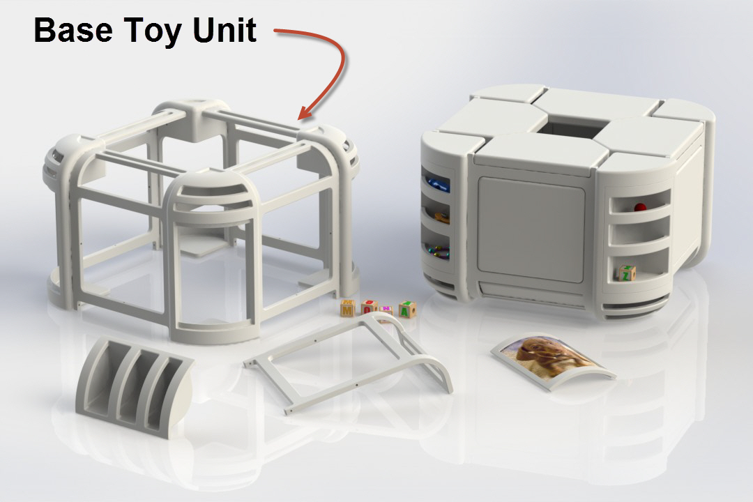
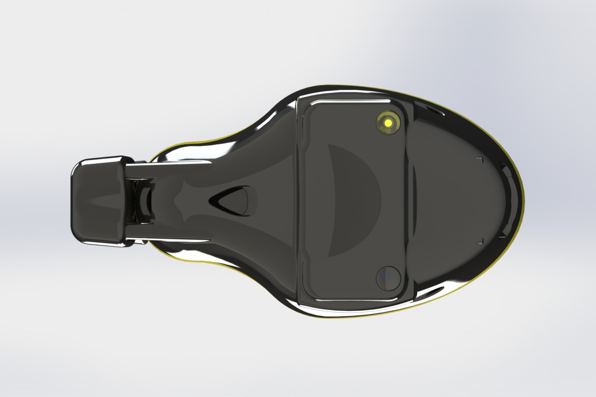
Designing the 3D-Printed ‘Base Unit’ that can be Modified by Others
After thinking about the ideas for a few days, I started drawing prototype designs in SolidWorks and came up with a base concept whereby others could design custom 3D-Printed parts to be added to this ‘Base Unit’.
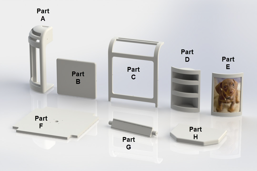
Custom Parts can be Designed & 3D-Printed by Parents
Possibly, parents would want to 3D-Print custom designed toy attachments … or maybe they would like to add frames for custom pictures of family members or favorite pets? There are even tri-shaped turning items on the upper area of the toy allowing for custom plastic laminated ‘paper-printed’ images to be slid into.
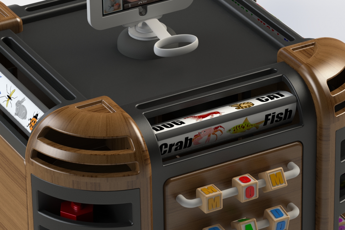
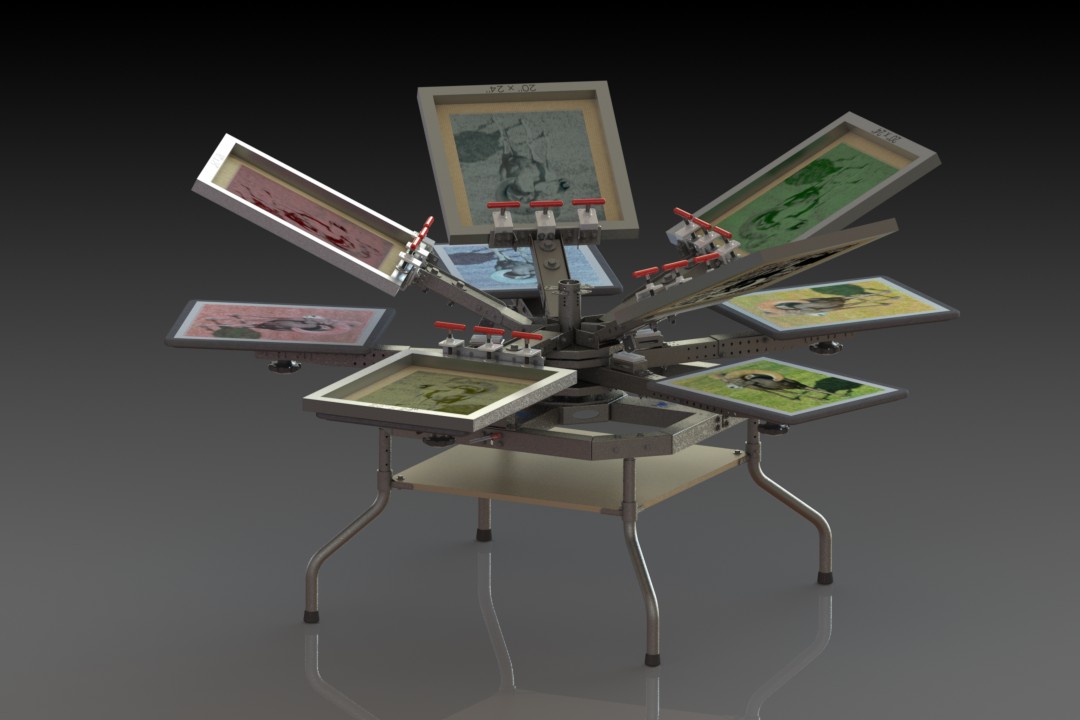
Turning Laminated Learning Labels can be Customized by Parents
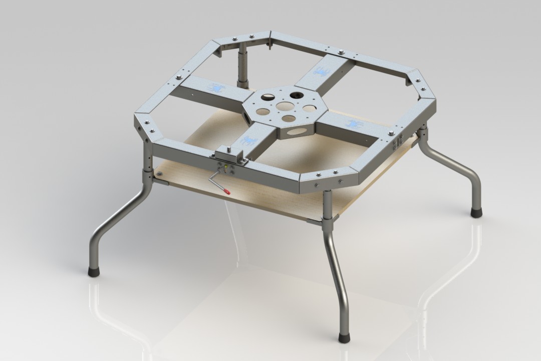
Once the child gets older the entire Toy Unit is flipped over and it becomes a Toy Box with lids that can open to be used as a play area Table/Workbench.
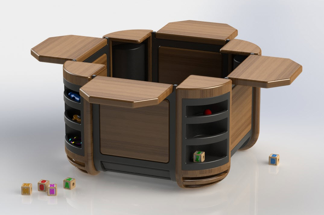
Flipped-Over Open Toy Box being used as a Play Workbench
As you can see in the SolidWorks rendering below, the sides can flip around 360 degrees for storage inside the toy. There are also mounting holes and room for different creative items to be designed for placement on the top of the unit.
The Toy Attachment Sides can be Turned Inside the Toy
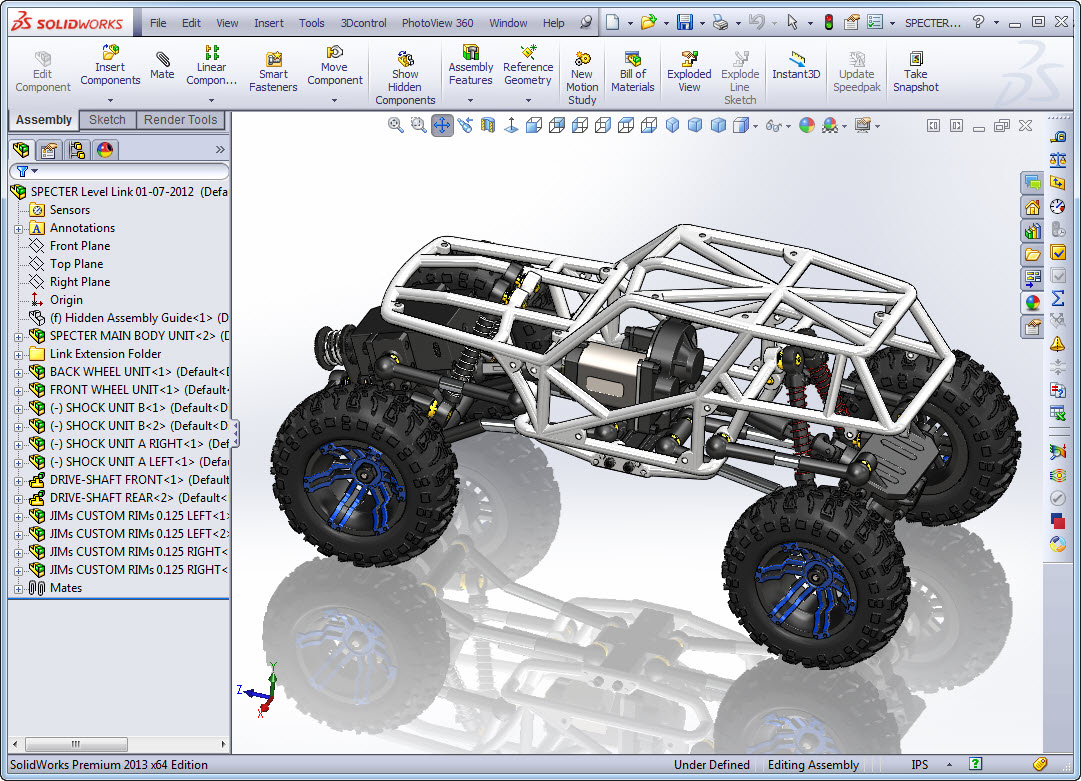
We used SolidWorks Simulation to test fit-up & strength of assembled parts.
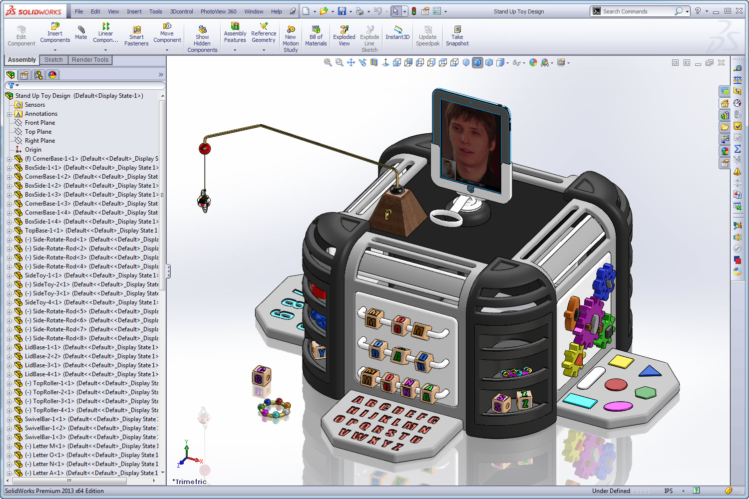
Screen-Capture image of the SolidWorks CAD Software
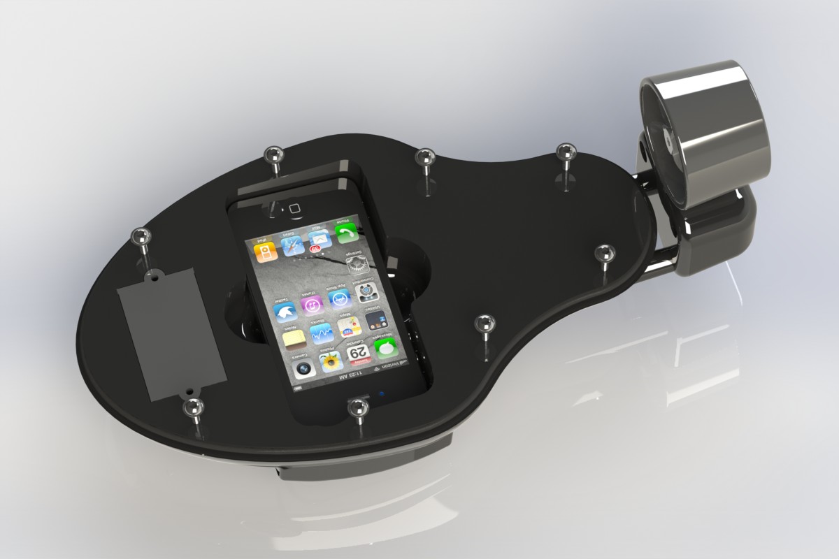
It was fun to try and think up what would interest a 6 to 18 month old child and I attempted to design items that where colorful, moved, and made noise. During the process I thought it might be nice to add a ‘surprise’ for Hardi. To me, it seemed as if he had to travel a lot for his work, and I thought it might nice to add a 3D-Printed iPad mount on the top of the toy to allow Hardi’s daughter to see and interact with him through ‘Facetime‘.
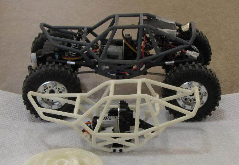
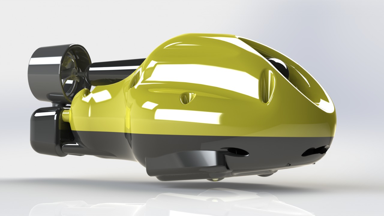
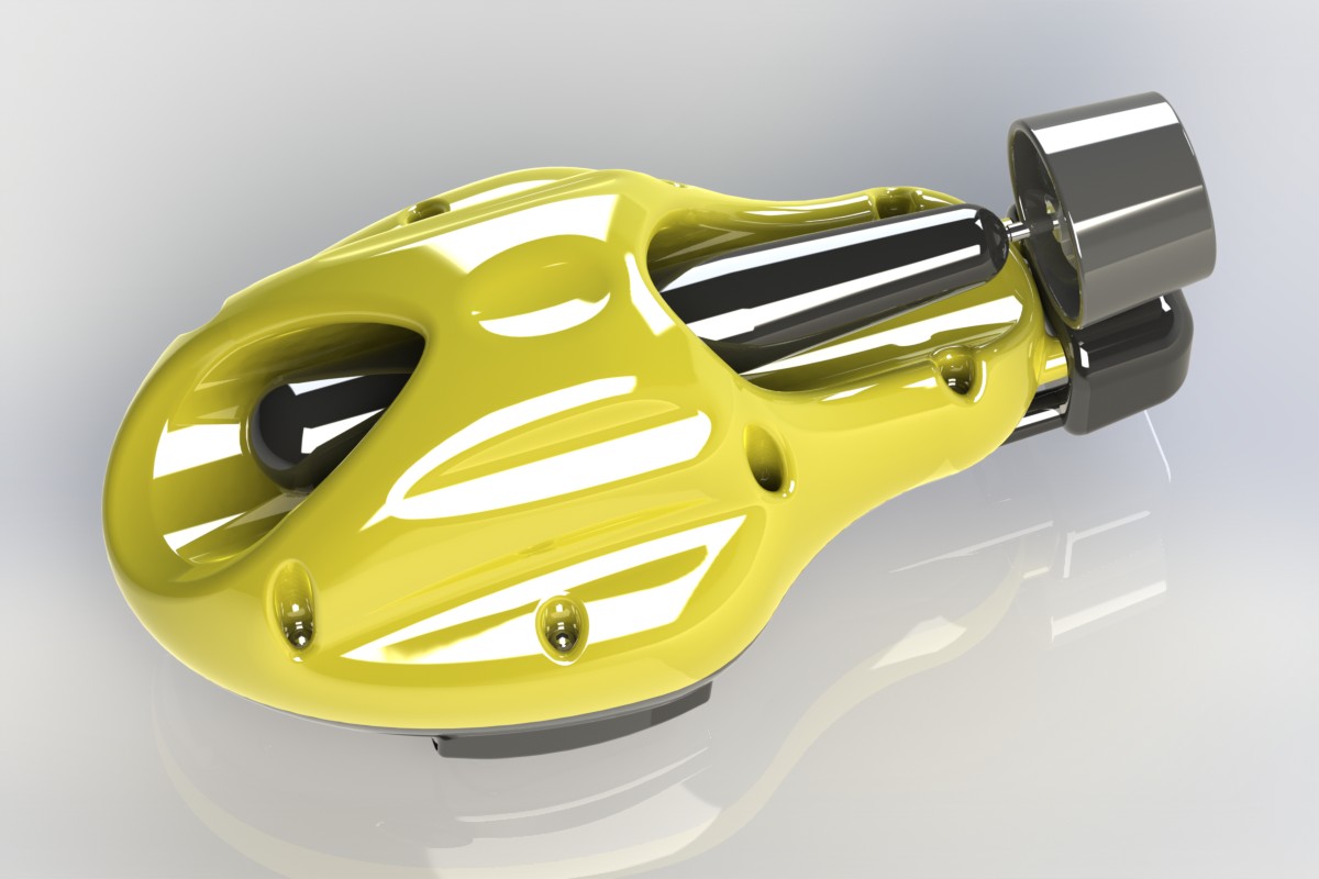
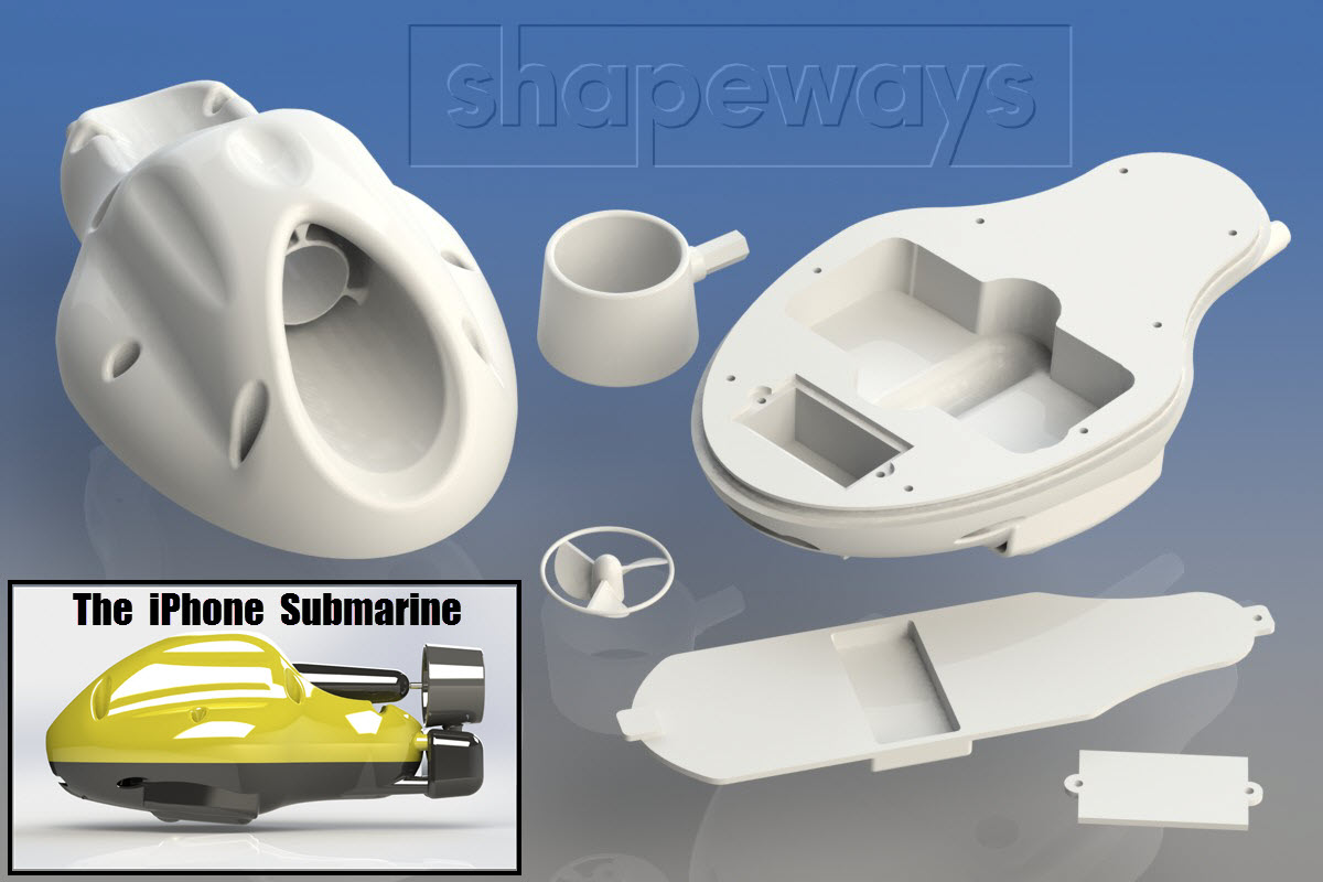
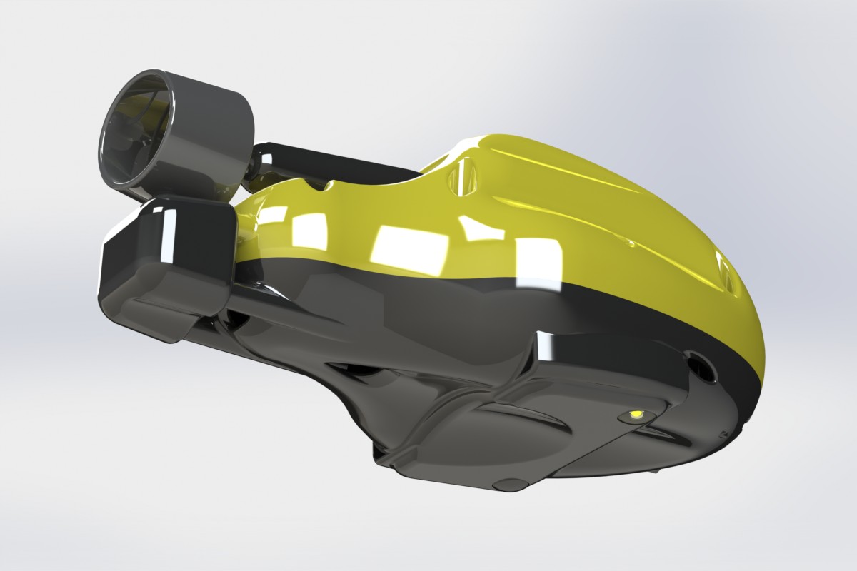
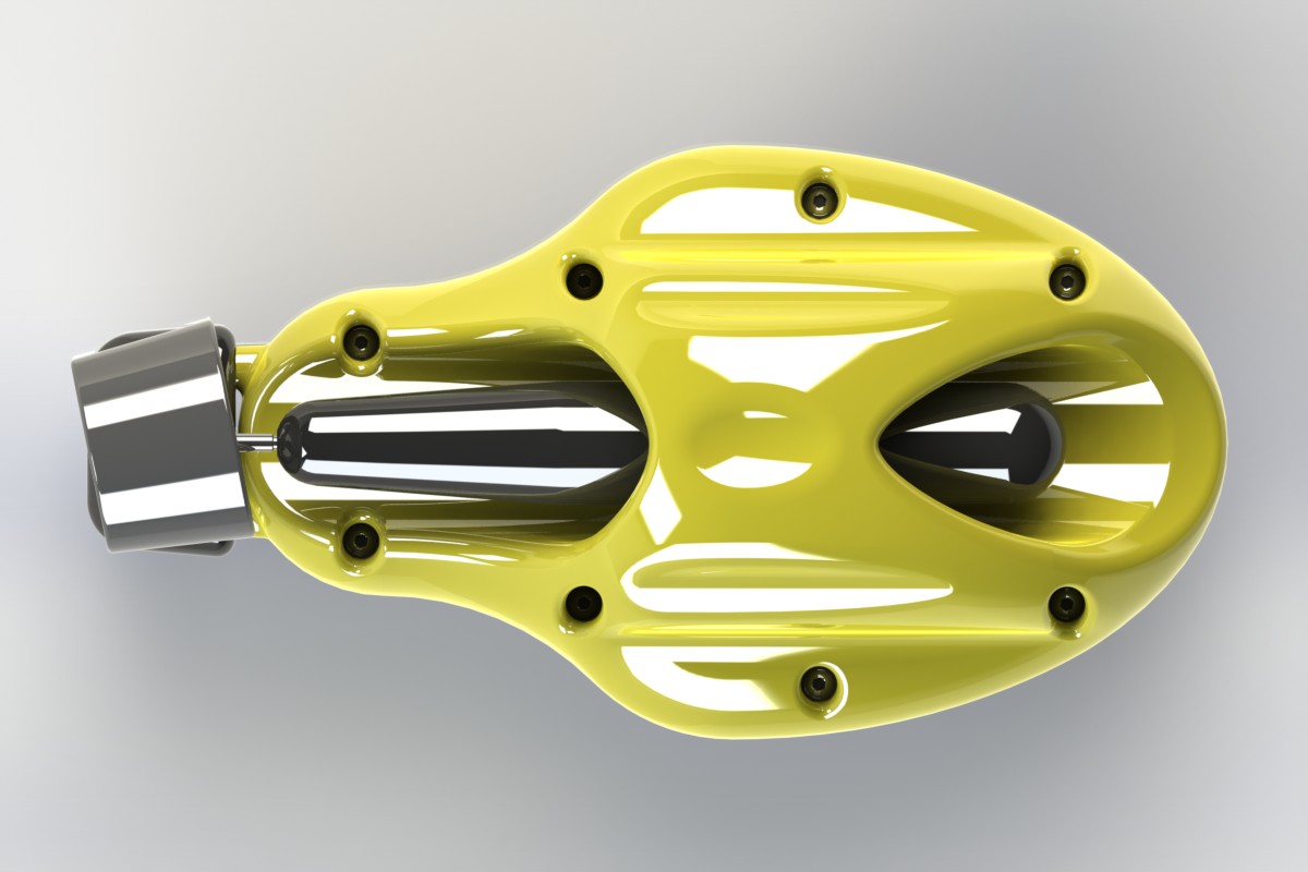
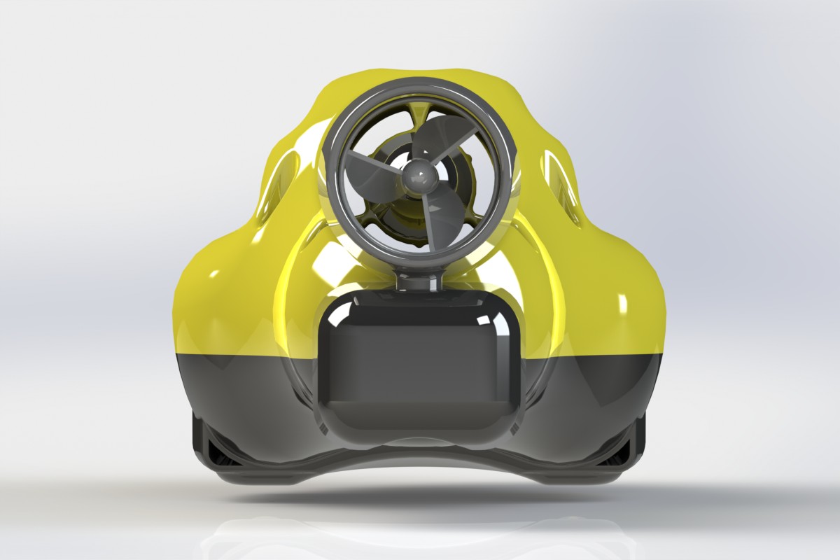
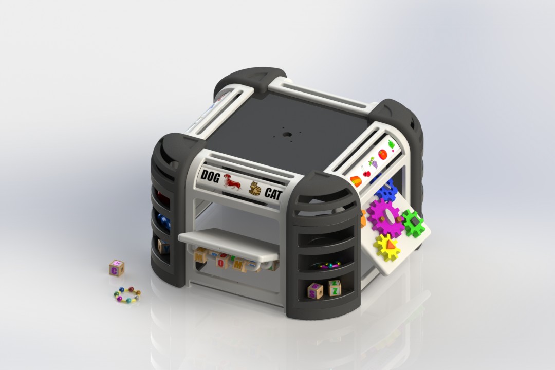
Another Version of the Toy made Completely from 3D-Printed Parts
The 3D-Printed mount holds an iPad, iPhone, or iPad Mini just out of reach of a small child’s hands… However, there is an easy to grasp handle that sticks out allowing the child to grab and move the iPad while interacting with the traveling parent via FaceTime. Hopefully, the child will see & hear their parent that is traveling and want to stand up to interact with the them using the toy to lean on.
I have no idea when the article in WIRED Magazine will come out or what it will include, but I thought it would be fun to explain why we did the Toy Project and to post of few more of the concept renderings on this blog.
JUST HAVING FUN!!
–CHEERS…